
Quick answer
Fiber optics is the technology of guiding light through extremely thin strands of transparent material, usually very pure glass. In communications, a transmitter converts information into an optical signal, the fiber carries that signal over distance, and a receiver converts the light back into usable electrical or digital data.
An optical fiber is not a hollow tube and the light does not simply travel through open space inside it. The light is guided by the optical properties of a central core and the surrounding cladding. The core has a slightly higher refractive index than the cladding, allowing light to remain confined to the fiber as a guided optical mode.
That combination of very low signal loss, huge available bandwidth, small size, and immunity to electromagnetic interference is why optical fiber has become one of the fundamental transmission media behind modern telecommunications, data centers, broadband networks, and submarine communication systems.
When to use this solution
Use this guide if you want to understand:
- what fiber optics means in simple terms;
- what an optical fiber and a fiber-optic cable actually look like;
- what the core, cladding, coating, strength members, and cable jacket do;
- why light does not immediately escape from a curved piece of glass;
- how an internet signal can be carried as light;
- why fiber can transmit large amounts of information over long distances;
- the difference between single-mode and multimode fiber;
- how fiber compares with copper and Wi-Fi;
- where fiber optics is used outside internet connections;
- why early optical fibers failed and how low-loss fiber became practical;
- what safety precautions matter when working around active fiber or bare glass fiber.
This is a conceptual and technical explainer, not an installation manual. If you are splicing, testing, terminating, or repairing a live fiber-optic system, use the procedures and safety rules specified for that equipment and network.
Before you start
You do not need a background in optics to follow this guide, but four ideas will make the rest easier:
- Light changes speed in different materials.
- A change in light speed can change its direction. This is refraction.
- Refractive index describes how strongly a material slows light compared with a vacuum.
- Attenuation means the optical signal becomes weaker as it travels.
One more distinction is important: the phrase fiber optics describes the technology. It is not the same thing as a particular home internet plan.
Fiber optics in simple words
A useful first picture is to think of an optical fiber as a road for light.
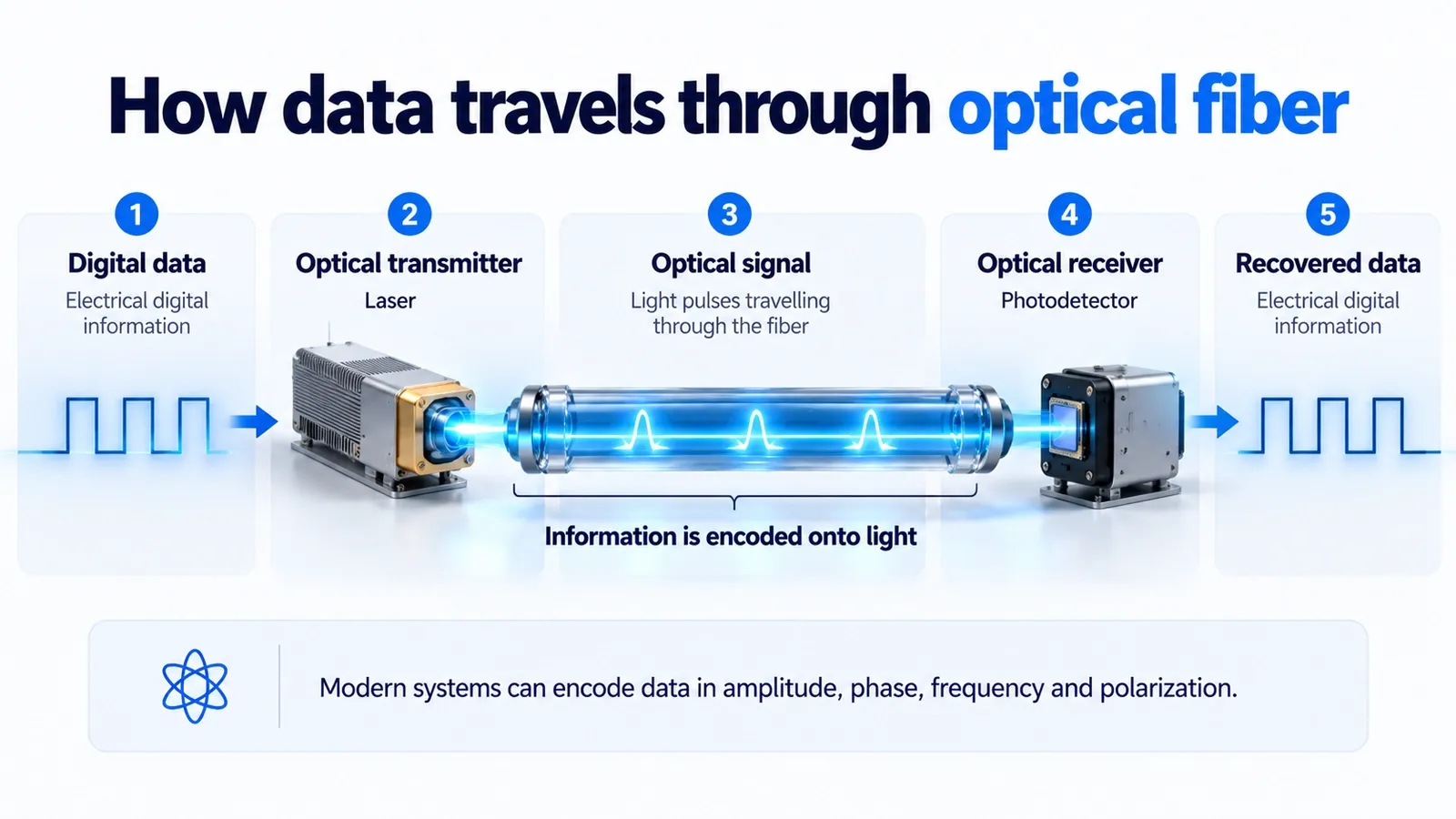
Instead of sending an electrical current through copper, a fiber-optic communication system launches controlled light into a very thin transparent waveguide. The information is encoded in changes to that light. At the other end, a photodetector measures the received optical signal and electronics recover the data.
This simple description is enough to understand the big idea:
information → optical transmitter → light in fiber → optical receiver → information
The science becomes more interesting when we ask the obvious question:
Why does the light stay inside such a thin piece of glass, even when the cable bends?
That is where the structure of the fiber matters.
Optical fiber, fiber-optic cable, fiber optics, and fiber internet are not the same thing
These terms are often mixed together, but they describe different things.
| Term | What it means |
|---|---|
| Fiber optics | The technology and field concerned with guiding light through optical fibers. |
| Optical fiber | The individual transparent waveguide that carries light. |
| Fiber-optic cable | A protected cable containing one or more optical fibers plus mechanical protection. |
| Fiber-optic line | A general term for a communication link that uses optical fiber. |
| Fiber internet | An internet access service that uses optical fiber somewhere in the access network. |
| FTTH | Fiber to the home: fiber reaches the subscriber’s premises rather than stopping farther upstream. |
| Wi-Fi | A local wireless networking technology that uses radio waves, not optical fiber. |
This distinction explains why asking whether “fiber is better than Wi-Fi” is not quite the right comparison. A home can receive internet service over fiber and then distribute that connection to phones and laptops over Wi-Fi.
What is a fiber-optic cable made of?
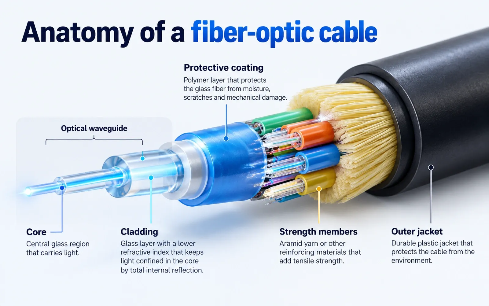
At the center of a communication fiber are two optical regions: the core and cladding.
Core
The core is the region in which most of the optical power is guided. In standard telecommunications fiber it is usually made from extremely pure silica-based glass whose composition is carefully controlled.
Cladding
The cladding is also usually glass. It surrounds the core and has a slightly lower refractive index. That index difference is essential to the fiber’s light-guiding behavior.
A common misconception is that the cladding is merely a plastic protective layer. It is not. The cladding is part of the optical waveguide.
Primary coating or buffer
Fresh glass fiber is mechanically vulnerable to surface damage. Protective polymer coatings are applied soon after the fiber is drawn. They help protect the glass from moisture, abrasion, and microscopic defects that could weaken it.
Strength members and cable jacket
A finished fiber-optic cable may contain additional elements such as aramid yarn, fiberglass strength members, loose tubes, water-blocking materials, armor, and an outer jacket. These features protect the optical fibers from pulling forces, crushing, water, sharp bends, and environmental damage.
The exact cable construction depends on whether the cable is designed for a building, a data center, an outdoor duct, direct burial, an aerial route, or a submarine system.
How do fiber optics work?
The beginner explanation is often reduced to one sentence:
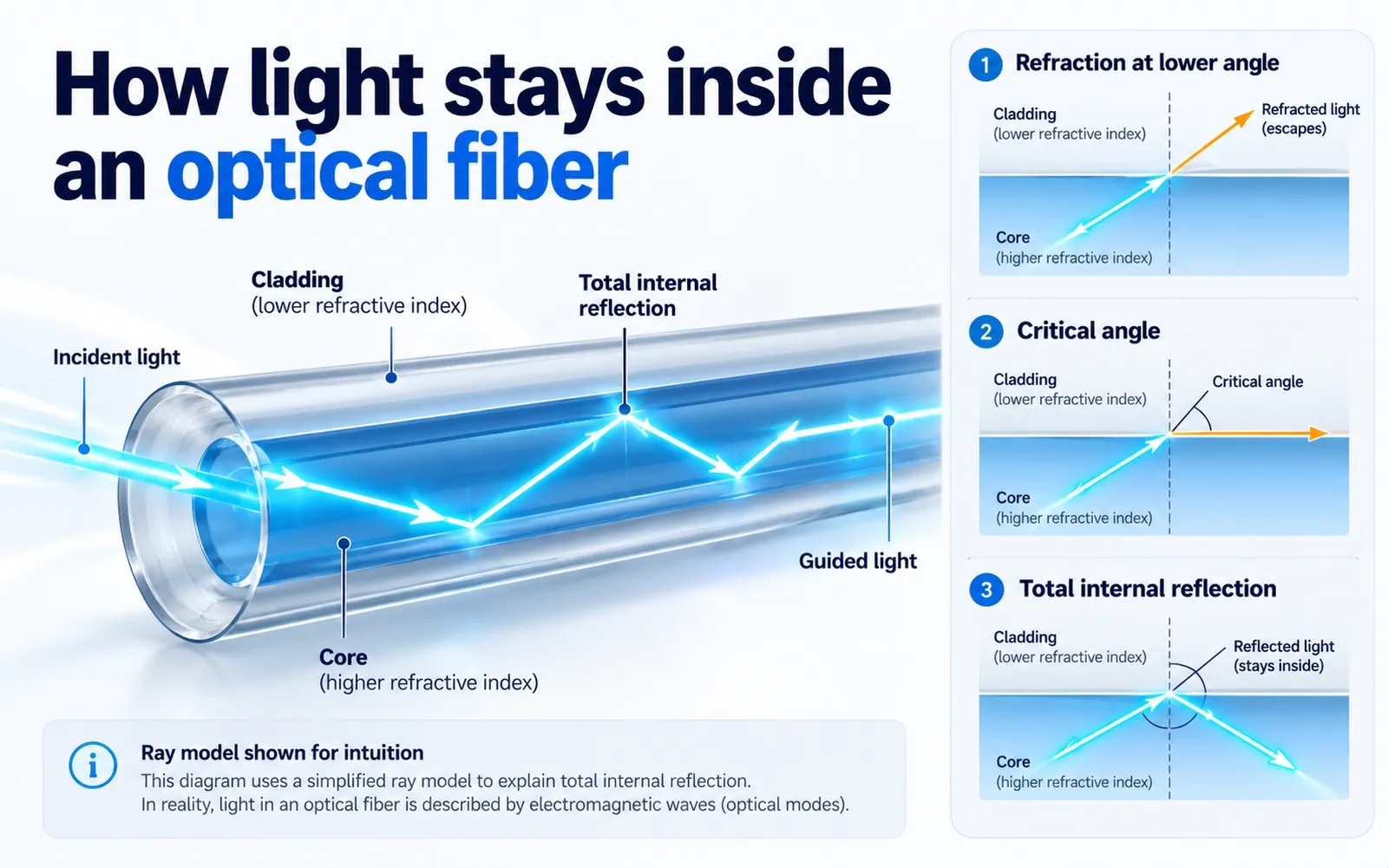
Light stays in the core because of total internal reflection.
That is useful, but it skips the steps that make the idea understandable.
1. Light changes speed when it enters a different optical material
Light travels fastest in a vacuum. In glass it travels more slowly.
The ratio between the speed of light in a vacuum and its speed in a material is called the material’s refractive index, usually written as n.
Silica glass used in optical fiber has a refractive index of roughly 1.46, depending on composition and wavelength. That means light travels through it at roughly two-thirds of its vacuum speed, not at 299,792 km/s.
2. A change in speed can bend the light
When a light wave reaches a boundary between two materials at an angle, part of the wave changes speed before the rest. The direction of propagation therefore changes.
This is refraction, described by Snell’s law.
3. From higher index to lower index, there is a critical angle
When light travels in a higher-index material toward a lower-index material, the refracted ray bends away from the normal.
As the incident angle increases, there is a point where the refracted ray would run along the boundary. That angle is the critical angle.
For still larger angles, the simple ray model predicts that no propagating refracted ray escapes into the second material. The light is reflected back.
This is total internal reflection.
4. The fiber is deliberately built with a higher-index core and lower-index cladding
The core and cladding are engineered so that light launched into the allowed range of angles can remain guided along the fiber.
That is the key design insight.
A bare glass rod surrounded by air can also guide light under the right conditions, but it is impractical: touching the surface, contamination, damage, and uncontrolled boundaries would disturb the optical behavior. A dedicated cladding creates a controlled optical boundary around the core.
A technical note: light does not literally behave like a tiny ball bouncing down the fiber
The “bouncing ray” picture is an excellent teaching model, especially for multimode fibers and geometrical optics.
But a real optical fiber is an electromagnetic waveguide. Its allowed field patterns are called modes. In a single-mode fiber, the full electromagnetic description is more accurate than imagining a single ray zig-zagging between the walls.
So “total internal reflection” is the right physical intuition, but guided-mode theory is the more complete description.
How can light follow a cable that bends?
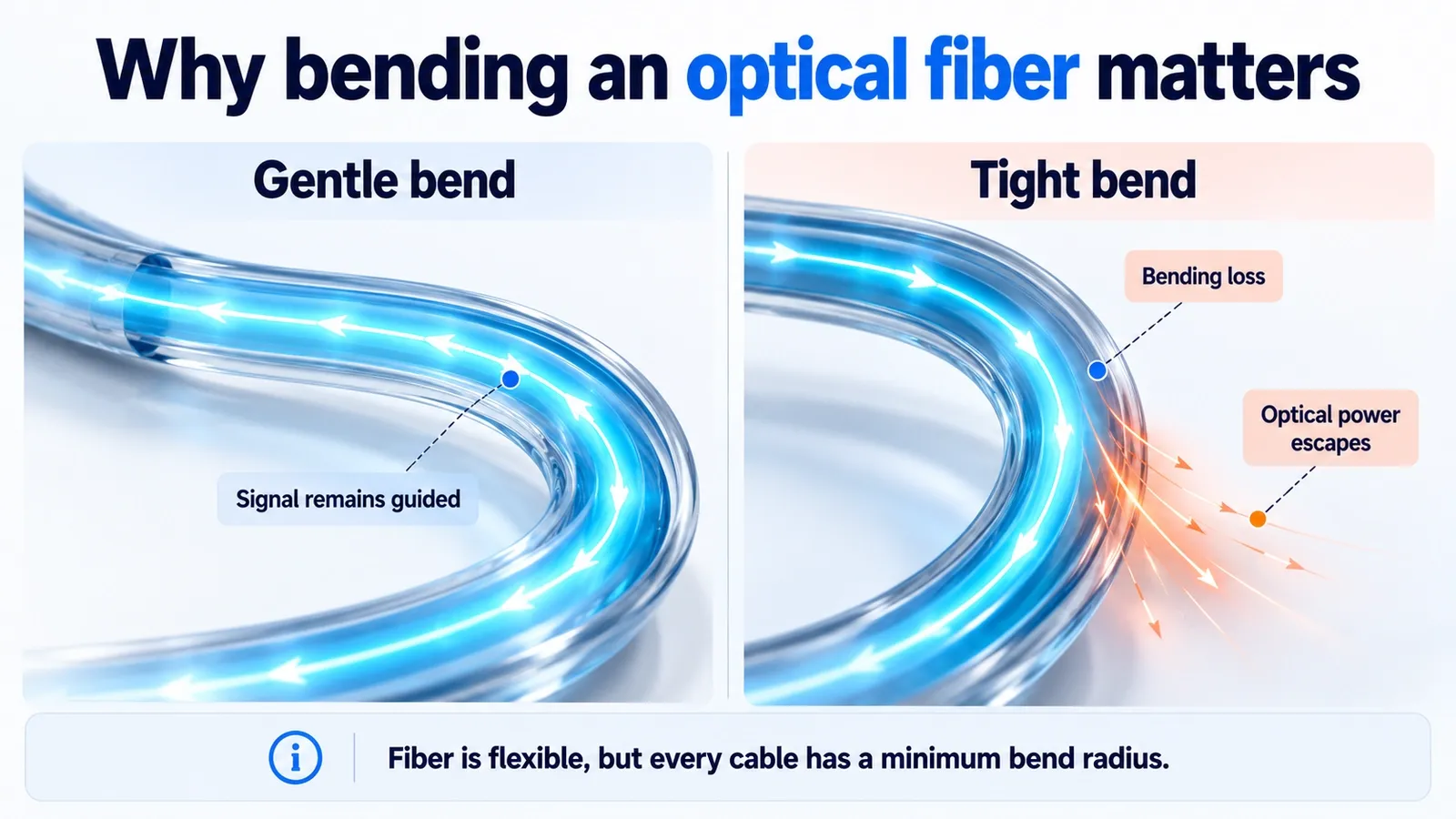
A moderate bend does not automatically make the signal fall out of the fiber because the core-cladding structure still supports guided propagation.
But bending is not free.
If a fiber is bent too tightly, the geometry of the guided field changes and some optical power can radiate away. This is called macrobending loss. Very small distortions, pressure points, or microscopic bends can also cause microbending loss.
Modern bend-insensitive fibers are designed to tolerate tighter routing than older designs, but every cable still has a specified minimum bend radius.
This gives us an important practical rule:
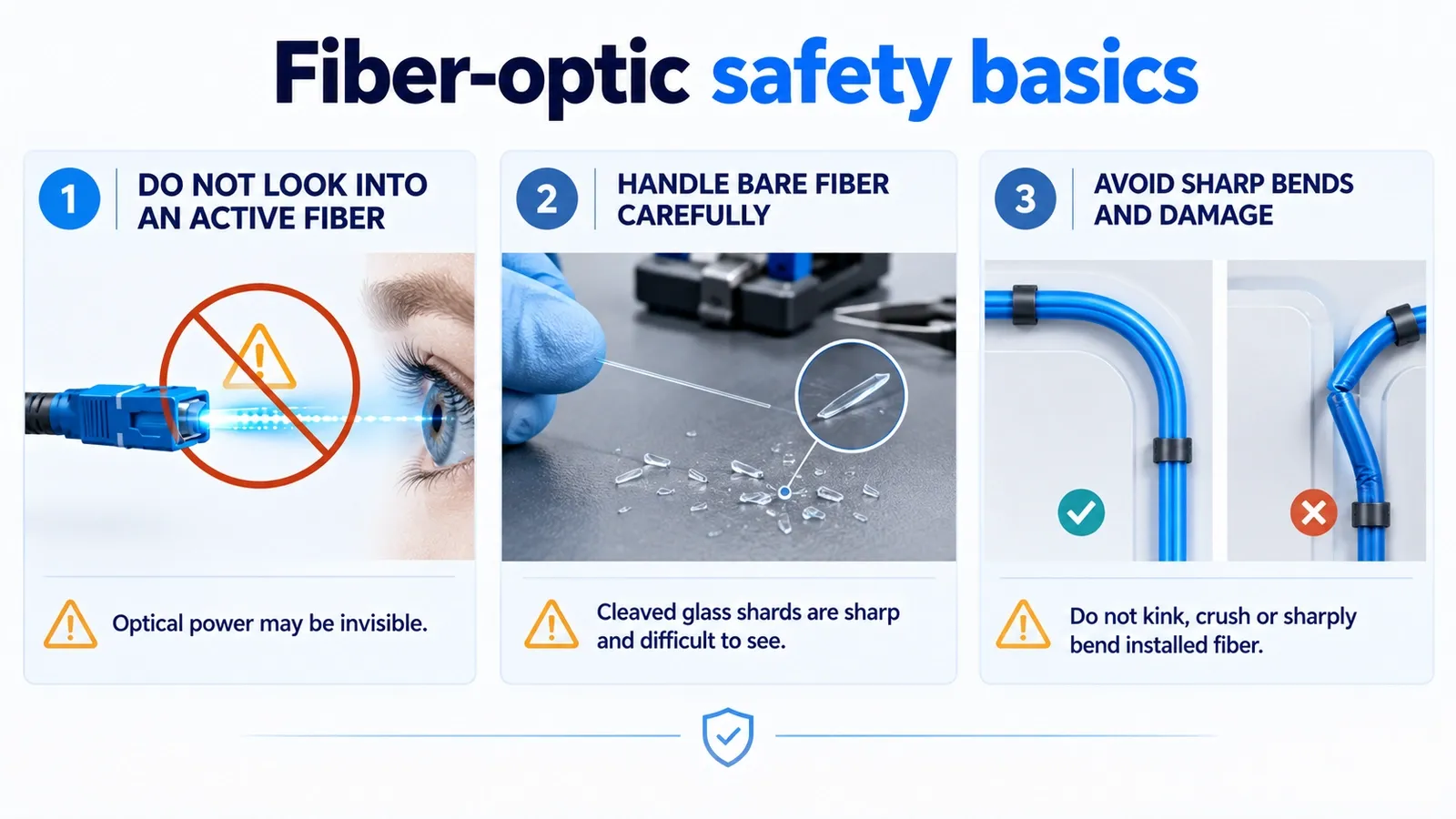
Fiber is flexible, but it is not meant to be kinked, knotted, crushed, or folded sharply.
How fiber carries data: step by step
The optical physics keeps the light in the fiber. The communications system gives that light meaning.
1. Data arrives at the optical transmitter
The original information may represent internet packets, a video stream, a phone call, storage traffic, sensor measurements, or another digital signal.
Electronics prepare that information for transmission.
2. A laser or LED produces the optical signal
The transmitter uses a light source, usually a semiconductor laser in high-speed telecommunications systems.
For a simple mental model, you can imagine light representing binary data: one optical state for a 1, another for a 0.
Real high-capacity systems are more sophisticated. Instead of relying only on “light on” and “light off,” they can encode information in controlled changes of optical amplitude, phase, frequency, or polarization.
3. The signal travels through the fiber
The optical signal propagates as one or more guided modes.
The fiber is not perfectly lossless. Some light is gradually lost through material absorption, Rayleigh scattering, bending, splices, connectors, and other imperfections.
Modern telecommunications fiber is extraordinarily transparent compared with the early experimental fibers. The current ITU-T G.652 recommendation specifies standard single-mode fiber for operation around the 1310 nm and 1550 nm regions; for G.652.D cable it specifies attenuation limits as low as 0.30 dB/km across 1530–1565 nm.
4. Long systems manage loss and dispersion
Over sufficiently long distances, optical signals require engineering to preserve their quality.
Systems may use optical amplifiers, regeneration, dispersion management, forward error correction, and carefully chosen wavelengths and modulation formats.
An amplifier boosts optical power, but it does not magically remove every impairment. Noise, chromatic dispersion, polarization effects, nonlinear effects, and component losses still matter in high-performance links.
5. A receiver converts light back into an electrical signal
At the destination, a photodetector responds to the arriving optical signal.
Receiver electronics then recover timing and data so that the information can be delivered to networking equipment, computers, storage systems, phones, or other devices.
Why can fiber carry so much information?
Three properties matter especially.
Enormous optical bandwidth
Visible and infrared light operate at frequencies enormously higher than traditional electrical voice-band signals.
High carrier frequency does not automatically mean infinite data capacity, but optical systems provide an exceptionally large spectral resource for communications engineering.
Low attenuation
A signal that weakens slowly can travel farther between active components.
The historical challenge was not proving that glass could guide light. Researchers had demonstrated light guiding long before modern telecommunications. The challenge was making glass pure and controlled enough that the signal did not disappear after a short distance.
Multiple wavelengths can share one fiber
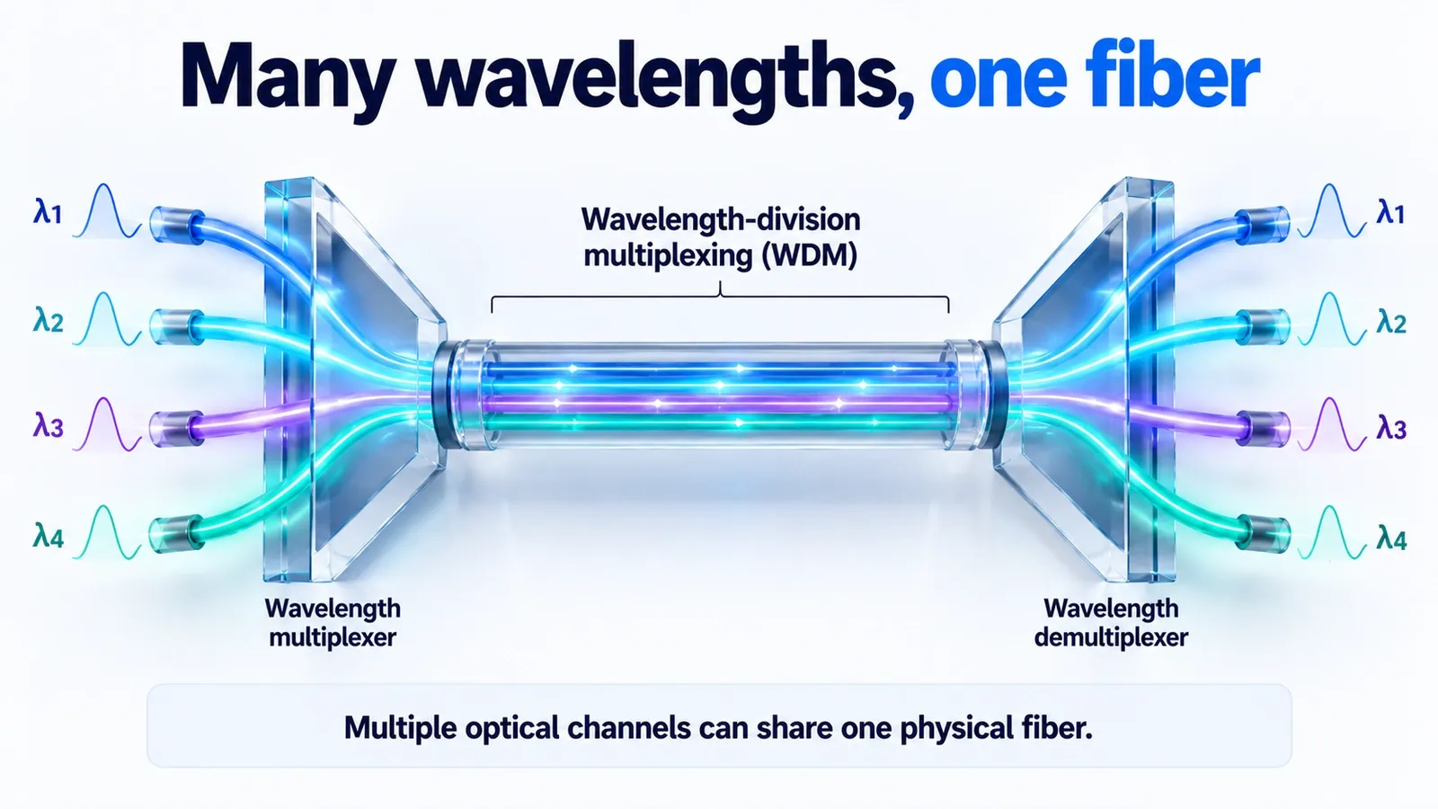
Modern networks can transmit several optical channels through the same fiber at different wavelengths. This is wavelength-division multiplexing (WDM).
Dense WDM systems can place many closely spaced optical channels on a single fiber, multiplying the capacity of the physical strand without installing a separate fiber for every channel.
This is one reason a hair-thin optical medium can become part of an infrastructure carrying enormous volumes of global traffic.
Single-mode vs multimode fiber
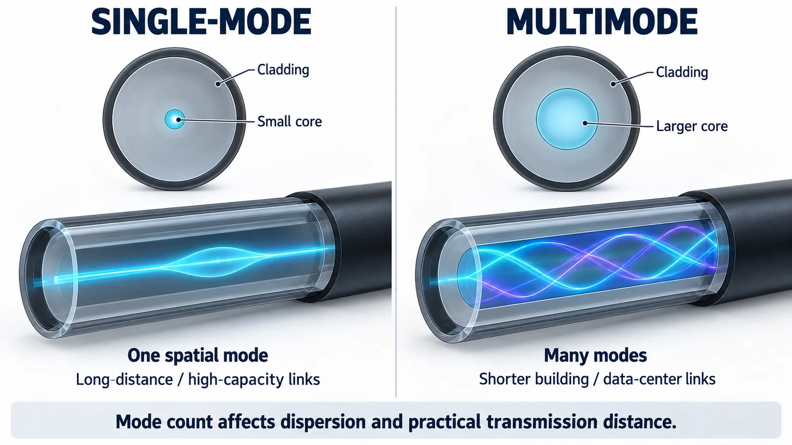
The two broad families used in communications are single-mode fiber and multimode fiber.
| Property | Single-mode fiber | Multimode fiber |
|---|---|---|
| Guided modes | Designed to support one fundamental spatial mode in its operating range | Supports many propagation modes |
| Core | Small | Larger |
| Typical use | Long-distance telecom, access networks, high-capacity links | Shorter building and data-center links |
| Common wavelengths | Often around 1310 and 1550 nm | Commonly 850 nm in modern short-reach systems |
| Main advantage | Very low modal dispersion and excellent long-distance performance | Easier coupling and practical short-reach optics |
| Main limitation | Tighter optical alignment and transceiver requirements | Modal dispersion limits distance/bandwidth compared with single-mode |
Are there three types of fiber-optic cable?
You will sometimes see a three-part classification:
- single-mode;
- multimode step-index;
- multimode graded-index.
That classification mixes mode count with refractive-index profile.
For most practical explanations, it is clearer to begin with the two main families — single-mode and multimode — and then explain that multimode designs can use different index profiles, including step-index and graded-index.
What are fiber optics used for?
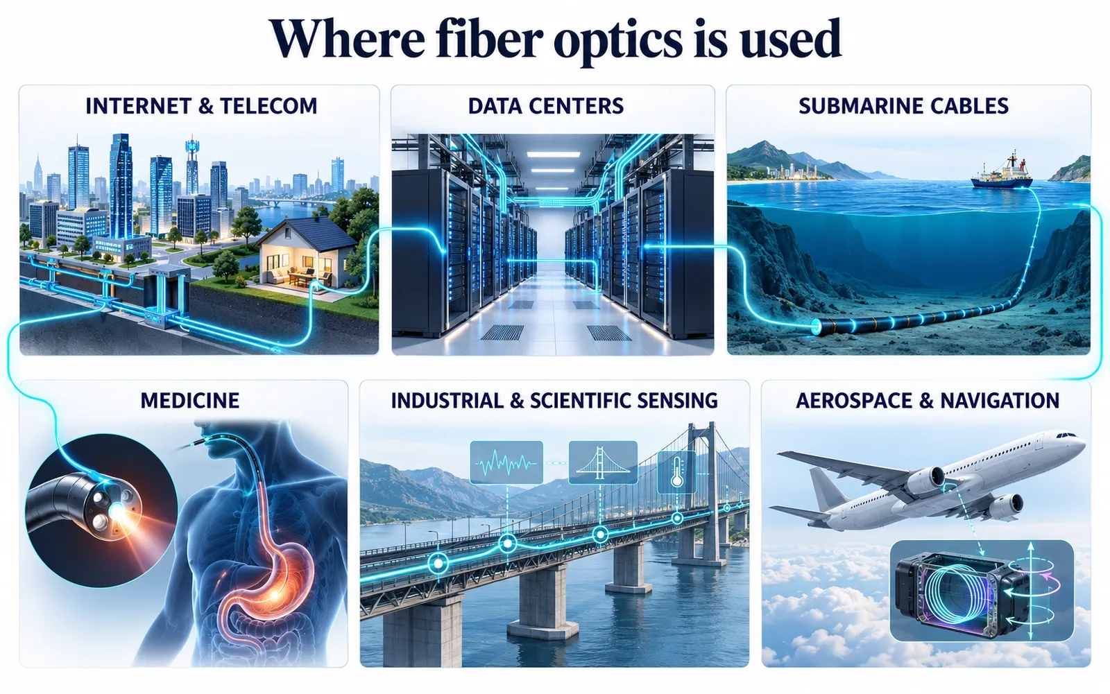
Telecommunications is the most visible application, but it is only one part of the field.
Internet and telephone networks
Fiber is used in long-haul networks, metro networks, broadband access, mobile-network backhaul and fronthaul, enterprise networks, and connections between network equipment.
Data centers
High-speed fiber links connect switches, servers, storage, and entire data-center buildings. At high data rates and large scale, optical links are essential for moving enormous amounts of data efficiently.
Submarine communication cables
Continents are interconnected by submarine cable systems that contain optical fibers, optical repeaters or amplifiers, power conductors for subsea equipment, and heavy mechanical protection appropriate to ocean conditions.
The fact that a home connection feels “wireless” does not mean the global internet is wireless. Much of the long-distance infrastructure behind it is optical fiber.
Medicine
Optical fibers and related fiber technologies are used for illumination, imaging bundles, minimally invasive instruments, and delivery of laser energy.
The exact fiber design for medical use may differ significantly from standard telecom fiber.
Industrial and scientific sensing
Fiber can act as more than a communications path. Optical-fiber sensors can measure strain, temperature, pressure, vibration, acoustic signals, and other physical quantities.
Fiber Bragg gratings, interferometric sensors, and distributed sensing systems are used in structures, energy systems, industrial environments, research, and monitoring.
Defense, aerospace, navigation, and precision measurement
Optical fiber is also used in fiber-optic gyroscopes, timing distribution, spectroscopy, metrology, laser systems, and other photonic instruments.
Fiber optics vs copper
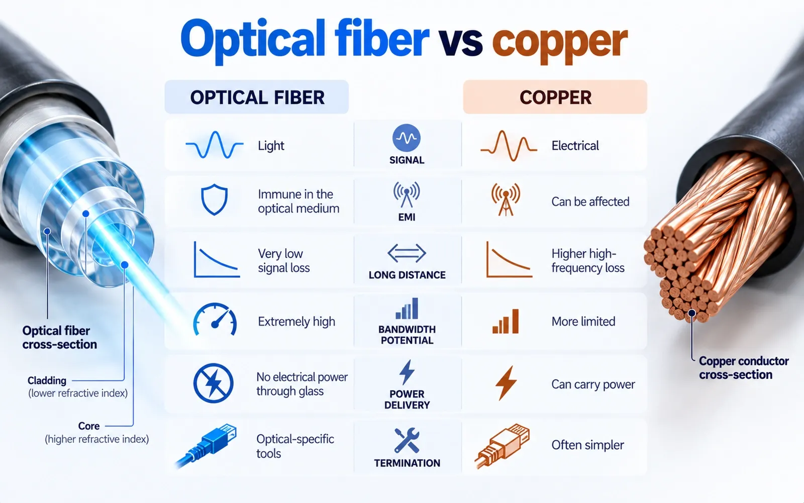
Fiber did not replace copper because copper “stopped working.” Copper remains useful for power delivery, short network links, low-cost wiring, and many other applications.
Fiber became essential because it solves a different set of problems extremely well.
| Factor | Optical fiber | Copper cable |
|---|---|---|
| Signal | Light | Electrical signal |
| Electrical conductivity | Non-conductive glass medium | Conductive metal |
| Electromagnetic interference | Immune in the optical medium | Can be affected depending on cable/system |
| Long-distance loss | Very low in telecom fiber | Higher at high frequencies |
| Bandwidth potential | Extremely high | More limited by electrical channel characteristics |
| Size/weight for high-capacity links | Very small/light | Generally larger/heavier for comparable high-capacity trunks |
| Power delivery | Cannot deliver conventional electrical power through the glass | Can carry electrical power |
| Termination/repair | Requires optical-specific tools and skills | Often simpler for common low-speed electrical cabling |
| Bend/physical damage | Sensitive to excessive bend, crush, and glass damage | Also has mechanical limits, but failure mechanisms differ |
Fiber’s immunity to electromagnetic interference is especially valuable around electrical equipment and for long links.
But copper has an important advantage in many local networks: a copper Ethernet cable can carry both data and electrical power using Power over Ethernet. A glass optical fiber cannot do that by itself.
Fiber vs Wi-Fi: they are not competitors
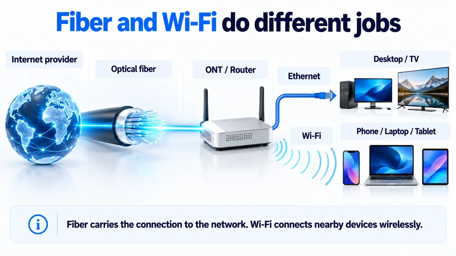
Fiber and Wi-Fi solve different parts of the connection.
A typical fiber-to-the-home path looks like this:
provider network → optical fiber → ONT/router → Ethernet and/or Wi-Fi → your devices
Fiber is the physical transmission medium carrying the connection to or through the premises.
Wi-Fi is a radio technology used to connect nearby devices without cables.
So if a home has fiber internet, it can still need Wi-Fi for phones, tablets, laptops, smart TVs, and other wireless devices.
This also explains why “my Wi-Fi is slow even though I have fiber” is possible. A fast fiber access link does not eliminate local problems such as weak Wi-Fi signal, interference, overloaded access points, slow devices, poor router placement, or limited Ethernet interfaces.
What are the disadvantages of fiber optics?
Fiber is an exceptional communications medium, but it has trade-offs.
Installation requires specialist techniques
Optical connectors must be clean and precisely aligned. Permanent joins often use fusion splicing. Testing requires optical instruments and trained interpretation.
Tight bends and mechanical damage can increase loss
A fiber may survive a gentle curve but perform badly or break if sharply bent, crushed, stretched beyond its rating, or damaged during construction.
The glass itself cannot power a device
A fiber link still requires powered transmitters, receivers, switches, optical network terminals, amplifiers, and routers.
Repairs can be more specialized
Finding a break, preparing the fiber, cleaning it, splicing it, and validating link loss require different tools from ordinary copper wiring.
Optics can be a significant part of system cost
The glass strand itself is only one component. Transceivers, connectors, splitters, amplifiers, splicing, testing, civil works, and network design all contribute to the total cost.
Are fiber-optic cables fragile or dangerous?
A finished cable is much tougher than an exposed hair-thin fiber.
The bare glass can have impressive tensile strength when its surface is pristine, but microscopic flaws, abrasion, sharp bending, and crushing can make it fail. That is why production fiber receives protective coatings and why installed fibers are packaged inside engineered cables.
The main safety risks are also easy to misunderstand.
Do not look into an active fiber
Many communications systems use infrared wavelengths that are invisible to the human eye. You cannot reliably determine whether a fiber is active by looking at it.
The Fiber Optic Association recommends verifying that no optical power is present before inspection, particularly before using a microscope, which can concentrate optical energy into the eye.
Bare fiber scraps are a real hazard
Tiny cleaved pieces of glass can be extremely sharp and difficult to see. Technicians use eye protection, controlled work surfaces, and dedicated containers for fiber scraps.
For normal users, an intact installed fiber cable is not something to fear. The safety concern applies mainly when cables are damaged, opened, tested, terminated, or spliced.
How are optical fibers made?
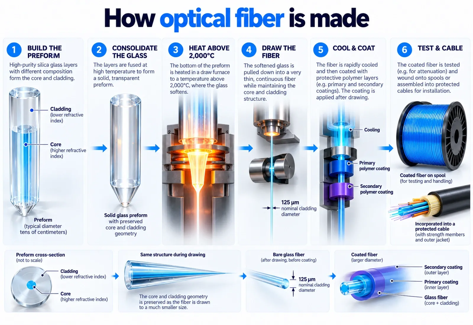
The manufacturing process is one of the most remarkable parts of the technology because the final product is extremely small, yet its optical composition must remain controlled over long distances.
1. Build a preform
Manufacturers first create a much larger glass structure called a preform.
Its cross-section already contains the optical design that the finished fiber needs: core and cladding regions with carefully controlled refractive indices.
High-purity silica is combined with precisely selected dopants to adjust refractive index and other properties.
Different manufacturers use different deposition processes, but the goal is similar: create an extremely pure, geometrically controlled glass preform.
2. Collapse and consolidate the glass
Deposited material is transformed into a solid, transparent glass structure.
Contamination and trapped defects must be tightly controlled because even tiny concentrations of unwanted material can increase optical loss.
3. Heat the preform in a draw tower
The lower end of the preform is heated above 2,000 °C until the glass becomes soft enough to draw.
Gravity and controlled pulling form a very thin continuous fiber.
Standard telecom single-mode fiber uses a nominal cladding diameter of 125 micrometres. The core is much smaller.
4. Control the diameter continuously
Sensors monitor the fiber while it is being drawn so that its geometry remains within tight tolerances.
The microscopic cross-sectional structure of the large preform is preserved as it is scaled down into the finished fiber.
5. Cool and coat the fiber
The glass must cool in a controlled way.
Protective polymer coatings are then applied before the pristine glass surface can accumulate significant damage.
6. Test and cable it
Manufacturers test optical attenuation, geometry, strength, and other properties.
The coated fibers can then be colored, grouped into ribbons or tubes, surrounded by strength members, protected from moisture, armored where required, and jacketed into finished cables.
Why early fiber optics did not work
This is the part of the story that explains why modern fiber is an engineering achievement rather than simply “a glass wire.”
By the early 1960s, lasers had made optical communication look attractive. Light offered frequencies vastly higher than traditional electrical communication channels.
But early glass fibers lost far too much light.
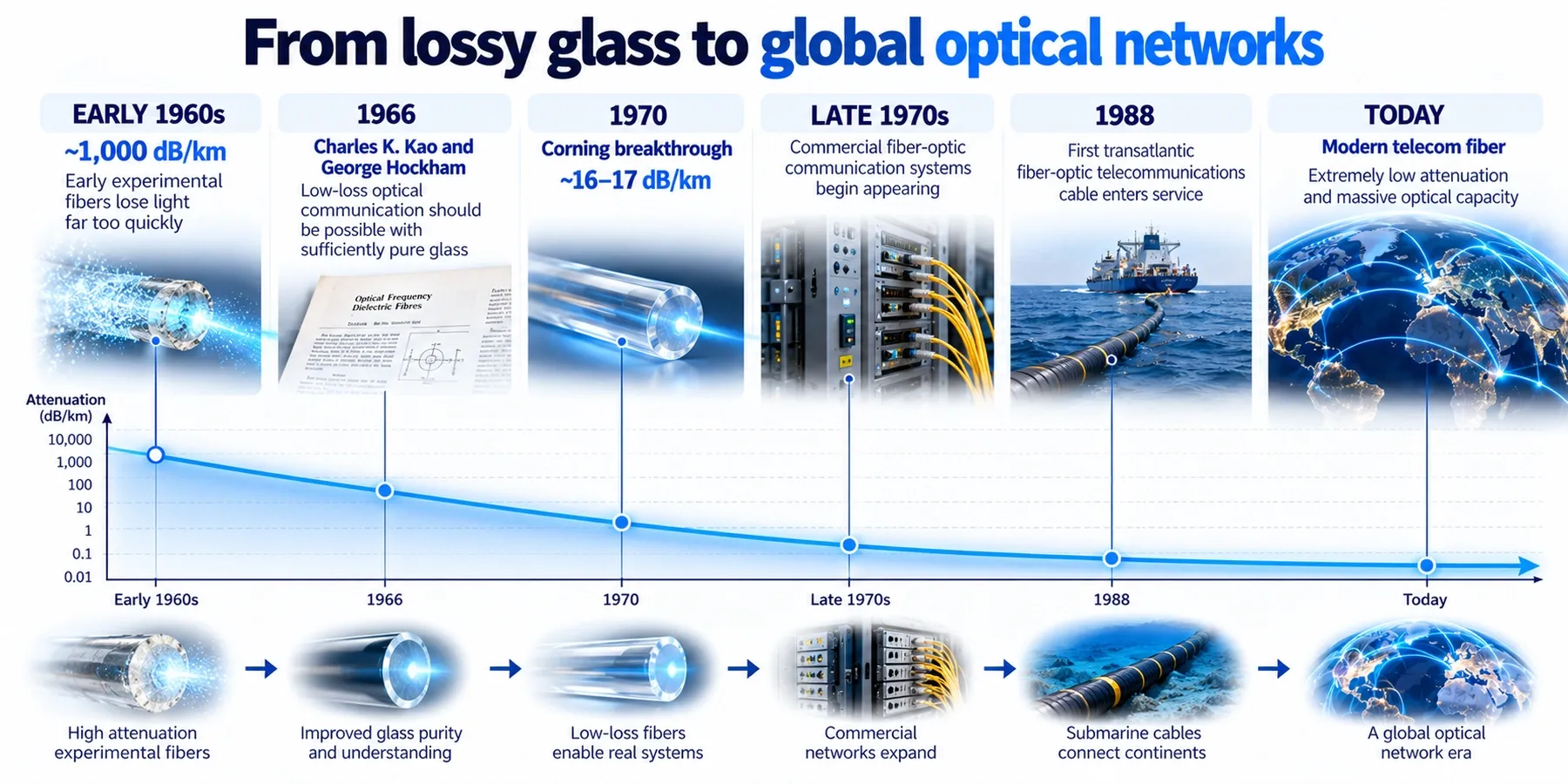
Some experimental fibers had losses around 1,000 dB per kilometre. A communication signal would become effectively useless over a very short distance.
The crucial question was whether that loss was a fundamental property of glass or the result of avoidable imperfections.
Charles Kao focused on the right problem
Charles K. Kao and George Hockham argued in 1966 that very low-loss optical communication should be possible if the material could be made sufficiently pure.
Kao’s work helped shift the challenge from:
“Glass loses too much light.”
to:
“Why does this glass lose so much light, and can we remove the cause?”
That change in question was decisive.
Scattering cannot be eliminated completely
Glass is an amorphous material rather than a perfect crystal. Microscopic density fluctuations scatter a small amount of light.
In high-purity silica, Rayleigh scattering is one fundamental source of attenuation, especially at shorter wavelengths.
It can be minimized through material and process control, but not reduced to zero.
Impurities can absorb light
Early glass contained trace contaminants that were insignificant for windows but disastrous for kilometres of optical propagation.
Transition metals and hydroxyl contamination can absorb specific wavelength ranges.
A window only needs to look transparent across a few millimetres. A telecommunications fiber must preserve an optical signal over kilometres.
That is an entirely different standard of transparency.
Who invented fiber optics?
There is no single moment when one person invented every part of fiber optics.
The history includes discoveries in geometrical optics, light guiding, glass fibers, medical imaging, lasers, materials science, semiconductor light sources, detectors, cable engineering, optical amplifiers, and digital communications.
For modern long-distance optical communication, however, two milestones are especially important.
Charles Kao established the path to low-loss optical communication
Kao received half of the 2009 Nobel Prize in Physics for “groundbreaking achievements concerning the transmission of light in fibers for optical communication.”
His work showed that the enormous losses in available fibers were not an unavoidable limit of the glass itself and that sufficiently pure material could make long-distance optical communication practical.
Corning demonstrated the first practical low-loss fiber
In 1970, Corning researchers Robert Maurer, Donald Keck, and Peter Schultz produced a fiber with roughly 16–17 dB/km of attenuation, beating the 20 dB/km target that had been considered necessary for practical communications research.
That number is enormous compared with modern telecom fiber, but it was the proof that the concept could work.
From there, manufacturing, material purity, wavelength selection, lasers, receivers, splicing, amplifiers, and network engineering improved rapidly.
By the end of the 1970s, commercial optical communication systems were appearing. In the following decades, fiber became the medium connecting cities, countries, data centers, mobile networks, and continents.
Why fiber optics changed the internet
The internet is not one network and it does not depend on one transmission technology.
But modern internet scale would be extremely difficult without optical fiber.
Fiber made it practical to build links that combine:
- long reach;
- low attenuation;
- very high capacity;
- electrical isolation;
- small physical cross-section;
- wavelength multiplexing;
- compatibility with optical amplification.
Those properties matter at every layer of large-scale connectivity: access networks, metro networks, data-center interconnects, national backbones, and submarine systems.
The transition was dramatic. Early telecom engineers were trying to fit more voice channels onto copper. Modern optical networks carry a mixture of video, cloud traffic, AI workloads, financial transactions, messaging, software downloads, mobile traffic, and countless other data streams.
The physical principle — guiding light through glass — is simple to state.
The engineering needed to do it reliably across the world is not.
Common mistakes
Mistake 1: “Fiber is a hollow glass tube with light travelling through the empty middle”
Standard telecommunications fiber is not a hollow pipe. The core is a solid transparent material, usually silica-based glass.
Mistake 2: “The plastic coating keeps the light inside”
The optical confinement comes from the relationship between the core and cladding. The outer polymer coating mainly protects the glass mechanically and environmentally.
Mistake 3: “The light literally bounces from wall to wall like a ball”
That is a useful ray-optics picture, but a fiber is an electromagnetic waveguide. Guided modes give the more complete physical description.
Mistake 4: “Light in fiber travels at the speed of light”
It travels at the speed of light in the glass, which is slower than the vacuum speed of light because the refractive index is greater than 1.
Mistake 5: “Fiber and Wi-Fi are competing alternatives”
A fiber connection and Wi-Fi commonly work together. One brings data through a wired optical network; the other connects nearby devices by radio.
Mistake 6: “Fiber has infinite bandwidth”
Fiber has enormous capacity, but real systems are limited by transceivers, amplifiers, noise, available spectrum, dispersion, nonlinear effects, modulation, error rates, switching equipment, and economics.
Mistake 7: “If the fiber bends at all, the signal escapes”
Normal cable routing includes bends. Problems arise when bend radius, pressure, or mechanical stress exceeds what the fiber and cable were designed to tolerate.
Security, privacy and safety notes
For a science explainer, the most important caution is physical rather than digital.
- Never look directly into the end of a fiber that could be connected to active equipment. The optical signal may be infrared and invisible.
- Do not use an inspection microscope on an unknown fiber until optical power has been checked with appropriate equipment.
- Bare glass fiber shards can penetrate skin and eyes. Professional fiber work requires safe handling and controlled disposal.
- Do not bend, cut, open, or attempt to splice an installed telecom cable unless you are trained and authorized to work on it.
- Underground and aerial cables may share routes with electrical, utility, or other hazardous infrastructure.
- An intact consumer fiber lead is normally handled like other delicate communications cabling: avoid crushing, kinking, pulling, and contamination of connector ends.
From a security perspective, fiber is not automatically “unhackable.” Physical tapping is more difficult and often more detectable than with some copper systems, but network security still depends on encryption, authentication, endpoint security, equipment configuration, and operational controls.
Faster alternative
If you only need the shortest accurate explanation, remember these five points:
- Fiber optics carries information using light.
- The light travels through a very pure glass or plastic waveguide.
- A higher-index core and lower-index cladding keep the optical field guided.
- Transmitters encode data onto light; receivers convert the optical signal back into data.
- Low loss and enormous optical bandwidth make fiber ideal for high-capacity, long-distance communications.
That is enough to understand the concept.
The rest of this article explains why those five statements are true.
FAQ
What is fiber optics in simple words?
Fiber optics is a way of sending light through very thin transparent fibers. In communications, the light carries encoded information such as internet data, video, or voice.
What are fiber optics made of?
Most telecommunications optical fibers are made from very pure silica-based glass. The central core is surrounded by glass cladding with a slightly lower refractive index. Polymer coatings protect the glass, and finished cables add mechanical protection such as strength members and jackets.
Is optical fiber made from glass or plastic?
Both exist. High-performance telecommunications networks mainly use silica glass fiber because it provides very low loss and excellent bandwidth. Plastic optical fiber is used in some short-distance, automotive, industrial, and consumer applications where its larger core and easier handling can be useful.
How does light stay inside a fiber?
The core has a higher refractive index than the cladding. This creates a waveguide that supports guided optical modes. Total internal reflection provides the standard intuitive explanation for why light remains confined instead of simply escaping through the side.
Does light bounce inside a fiber?
In ray optics, it can be represented as repeated total internal reflections. In a full electromagnetic description, however, light propagates as guided modes with electromagnetic fields extending through the core and partly into the cladding.
How fast does light travel in fiber?
Slower than in a vacuum. With a refractive index around 1.46, the propagation speed is roughly 200,000 km/s, although the exact group velocity depends on fiber composition and wavelength.
What is the difference between single-mode and multimode fiber?
Single-mode fiber is designed to carry one fundamental spatial mode and is preferred for long-distance and high-capacity links. Multimode fiber has a larger core and supports many modes, making it useful for shorter links such as those inside buildings and data centers.
What are the three types of fiber-optic cable?
There is no single universal “three types” classification. A common educational grouping is single-mode, multimode step-index, and multimode graded-index. In practice, it is clearer to treat single-mode and multimode as the two main fiber families and describe step-index or graded-index as refractive-index profiles.
Is fiber better than copper?
For high-capacity and long-distance data transmission, fiber has major advantages: low attenuation, high bandwidth, small size, and immunity to electromagnetic interference. Copper remains useful where cost, short distances, established infrastructure, or electrical power delivery are important.
Is fiber the same as Wi-Fi?
No. Fiber is a wired optical transmission medium. Wi-Fi is a wireless local networking technology based on radio. A home can use fiber for the internet connection and Wi-Fi to connect devices inside the home.
Do I still need Wi-Fi if I have fiber internet?
Only if you want wireless connectivity for your local devices. You can also connect devices by Ethernet. Fiber internet describes the provider-side access medium, while Wi-Fi describes the local wireless connection.
Does fiber need electricity?
The glass fiber itself does not need electrical power to guide light. The devices on the network do: lasers, receivers, switches, routers, optical network terminals, and amplifiers require power.
Why can fiber internet still feel slow?
The fiber link may not be the bottleneck. Wi-Fi interference, router performance, device limitations, server congestion, Ethernet port speed, network configuration, or the subscribed service rate can all reduce the speed experienced by a user.
Can a fiber-optic cable break?
Yes. Finished cables are engineered to be strong, but excessive pulling, crushing, sharp bending, impact, excavation damage, or poor handling can break fibers or increase optical loss.
Is it safe to touch a fiber-optic cable?
An intact, closed cable is generally safe to handle normally. Bare glass fiber and active optical connectors require more caution. Never stare into an unknown fiber end, and trained technicians should use proper procedures for shards, testing, stripping, cleaving, and splicing.
Are fiber-optic cables a fire hazard?
The glass fiber itself is not carrying electrical current like copper conductors, but cable jackets and other materials have fire-performance ratings appropriate to their installation environment. Some hybrid cables also contain metallic conductors. Building and fire codes still apply.
Will fiber optics become obsolete?
The equipment and modulation technologies around fiber will continue to evolve, but optical fiber remains exceptionally well suited to high-capacity communications. Existing fibers can often support generations of faster transmission equipment, which is one reason fiber infrastructure can have a long useful life.
Last tested
Reviewed against:
- Fiber Optic Association optical-fiber reference material
- Fiber Optic Association safety guidance
- ITU-T Recommendation G.652 (2024 revision)
- Nobel Prize documentation for Charles K. Kao
- Corning optical-fiber history and technical education material
- NIST material on optical-fiber sensing applications
Last tested: 2026-10-29
Related guides
Carefully selected guides to help you understand the topic and complete the next useful step.